Browse the products below by using the tabs to view different product categories and scroll down to show the full range of products.
14-Bit Digitizers
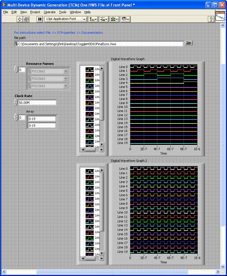
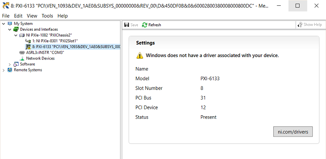
div > .uk-panel', row:true}'>Digital input/output port y on connector x, where y is the port number and x is the connector number. A port is made up of eight digital channels. Use an FPGA I/O Node configured for reading or writing, or use the Set Output Data or Set Output Enable method to access this port. PXI/PXIClk10: Controls the 10 MHz clock on the PXI backplane. At the PXI chassis DVI-I end, i have used a DVI-I to VGA and used VGA cable into the Monitor 2, it works. Also i have directly input DVI-D Cable into the DVI-I connector, and it DOESNT work. Hence i am suspecting that my graphics adaptor isnt outputting video on the Digital part of DVI-I.
ADQ7DC
- Single/dual channel
- Up to 10 GSPS sampling rate
- Up to 3 GHz input bandwidth
- DC-coupled
ADQ14DC
- Single/dual/quad channel
- Up to 2 GSPS sampling rate
- Up to 1.2 GHz input bandwidth
- DC-coupled (variable input range/gain optional)
ADQ14AC
- Single/dual/quad channel
- Up to 2 GSPS sampling rate
- Up to 1.2 GHz input bandwidth
- AC-coupled
ADQ14OCT
- Single channel
- 2 GSPS sampling rate
- 500 MHz input bandwidth
- DC-coupled
- Optimized for swept-source OCT, supporting variable K-clock

SDR14
- Dual inputs, dual outputs
- 800 MSPS input rate, 1.6 GSPS output rate
- 550 MHz input bandwidth, up to 800 MHz output bandwidth
- AC-coupled (DC-coupling optional for output)
ADQ1600RF
- Single channel
- 1.6 GSPS sampling rate
- 750 MHz input bandwidth
- AC-coupled
- Optimized for RF applications requiring high input bandwidth
ADQ1600TD
- Single channel
- 1.6 GSPS sampling rate
- 680 MHz input bandwidth
- AC-coupled
- Optimized for time-domain applications
ADQ114
- Single channel
- 800 MSPS sampling rate
- 850 MHz input bandwidth
- AC-coupled
ADQ214-DCLN
- Dual channel
- 400 MSPS sampling rate
- 100 MHz input bandwidth
- DC-coupled
- Optimized for low-noise measurements
ADQ214
- Dual channel
- 400 MSPS sampling rate
- Up to 850 MHz input bandwidth
- AC- and DC-coupled (software selectable)
12-Bit Digitizers
div > .uk-panel', row:true}'>ADQ32NEW!
- Dual channel
- 2.5 GSPS sampling rate
- 1 GHz input bandwidth
- DC-coupled
ADQ7WB
- Dual channel
- Up to 5 GSPS sampling rate
- 6.5 GHz input bandwidth
- AC-coupled
ADQ412
- Dual/quad channel
- Up to 4 GSPS sampling rate
- Up to 2 GHz input bandwidth
- AC-coupled
ADQ412DC
- Dual/quad channel
- Up to 4 GSPS sampling rate
- Up to 925 MHz input bandwidth
- DC-coupled
10-Bit Digitizers
div > .uk-panel', row:true}'>ADQ8-8C
- 8 analog channel
- 1 GSPS sampling rate
- 500 MHz input bandwidth
- DC-coupled
Pxi Input Devices Driver Updater
ADQ8-4XNew!
- Dual/quad channel
- Up to 4 GSPS sampling rate
- 1 GHz input bandwidth
- DC-coupled
8-Bit Digitizers
div > .uk-panel', row:true}'>ADQ108
- Scheduled for termination
- Single channel
- 7 GSPS sampling rate
- 2 GHz input bandwidth
- AC-coupled

ADQ208
Pxi Input Devices Driver Win 7
- Scheduled for termination
- Dual channel
- 4 GSPS sampling rate
- 2 GHz input bandwidth
- AC-coupled
Waveform Generators
div > .uk-panel', row:true}'>
SDR14
- Not recommended for new designs
- Dual inputs, dual outputs
- 800 MSPS input rate, 1.6 GSPS output rate
- 550 MHz input bandwidth, up to 800 MHz output bandwidth
- AC-coupled (DC-coupling optional for output)
SDR14TX
- Dual outputs
- 2 GSPS sample rate
- Up to 1.8 GHz output bandwidth
- DC-coupled, single-ended and differential
Extension Modules
div > .uk-panel', row:true}'>ADQ10GBE
- 10 Gbit Ethernet card
- PXIe form factor
ADQDSU
- Not recommended for new designs
- SSD disk storage unit for high-speed data recording
- Up to 2 TBytes total storage
- Up to 1 GBytes/s write speed
ADQDSP
- Scheduled for termination
- FPGA computational board
- Xilinx Virtex 6 LX240T
ADQTDU

- Not recommended for new designs
- Trigger/clock distribution for intra-board synchronization
- Single input and 6 outputs
- CMOS or LVPECL (AC-coupled LVPECL available as option)
| PRODUCT INFORMATION | |
|---|---|
| 1) Depending on sampling rate option. | |
| Resolution | 12 bit |
| Input signal range | 800 mVpp |
| Input channels | 2/4 (Dual/Quad Channel Mode) |
| Trigger | Software/Ext./Level |
| Clock | Int. / Ext. (SMA) 2 Vpp |
| Clock reference | Int. / Ext. 10 MHz / PXIe |
| Interfaces | USB, cPCIe/PXIe, PCIe, MTCA.4 µTCA |
| Dual Channel Mode | |
| Sample rate1) | 2.0 / 3.6 / 4.0 GSPS |
| Input bandwidth | 1.3 GHz |
| Memory size | 350 MSamples/channel |
| Quad Channel Mode | |
| Sample rate1) | 1.0 / 1.8 / 2.0 GSPS |
| Input bandwidth | 2 GHz |
| Memory size | 175 MSamples/channel |
Overview
The ADQ412 is a 2/4 (Dual/Quad) channel flexible digitizer that offers an outstanding combination of high bandwidth and dynamic range, which enables demanding measurements such as RF/IF sampling of very wide band signals. The high sampling rate is enabled by SP Devices' proprietary interleaving technology ADX.
Analog Front End (AFE)
The AFE of ADQ412 is AC-coupled and optimized for spectral purity over a wide bandwidth. The lower cut-off frequency is as low as 6 kHz and the bandwidth is set by the mode of operation. See the product information table to the right for more information.
Interface to the Host
The digitizer connects to the host via a high-speed USB 3.0 cable for easy to use standalone operation. Compact PCI Express / PXI Express or MTCA.4 µTCA interface is available for systems integration as a modular instrument. A PCIe version for integration into a PC is also available. All interface types allows for streaming of data at high transfer rates.
3-year warranty on SP Devices' products
Buy with confidence - our products are manufactured to the highest standards of quality and technology.
Features
Software Development Kit (SDK)
The ADQ412 comes with an easy-to-use API that allows easy integration into any application. Software tools for application development include C/C++, Matlab and DLLs for Windows XP/Vista. The SDK also includes SP Devices´ data capture tool, ADCaptureLab.
FPGA and the ADQ Development Kit
The ADQ412 is built on the ADQ DSP computational board which employs a Xilinx Virtex 6 LX240T FPGA. The user can access the FPGA and implement customized digital signal processing by purchasing the ADQ Development Kit. This kit contains everything that is needed to get started with the FPGA development, and also includes examples and documentation. See the ADQ DSPproduct page for more information.
Acquisition Functions
Standard trigger options are external, internal, software and level trigger. For PXIe units the backplane triggers are also available. The multi-record mode can be combined with any trigger function. Every record is tagged with a header containing time stamp (timing information), record counter, trigger counter and the trigger type for the record.
ADQ Design Services
SP Devices' offers the possibility of customizing the ADQ series digitizer boards. Customizations can include hardware, software and FPGA firmware changes. Read more about our design services here.
Further Information
For further information, download the datasheet here, and you will be contacted by our sales department.
Related Products
ADQ7DC
New Digitizer: 14-bit, 10 GSPS digitizer platform, 1-2 channels, open FPGAADQ14
Data Acquisition Unit - Digitizer: 14-bit, 2 GSPS digitizer platform, 2-4 channels, open FPGA - cPCI/PXI Express & USB3ADQ14OCT
Data Acquisition Unit - Digitizer: 14-bit, 1 GHz Swept-Source Optical Coherence Tomography platform - PCI Express & USB3SDR14
Combined Digitizer & Generator - 2 Analog Inputs - 2 Analog Outputs - PXI/PCI Express & MTCA.4 Micro-TCAADQ214-DCLN
Data Acquisition Unit - Digitizer: Low noise, 14 bit 400 MSPS - Dual Channel - cPCI/PXI Express & USBADQ214
Data Acquisition Unit - Digitizer: 14 bit 400 MSPS - Dual Channel - cPCI/PXI Express & USBADQ114
Data Acquisition Unit - Digitizer: 14 bit 800 MSPS - cPCI/PXI Express & USBADQ412
USB, PXI/PCI Express and MTCA.4 Micro-TCA Digitizer ADQ412 12b 4Ch 3.6 GSPSADQ412DC
USB, PXI/PCI Express and MTCA.4 Micro-TCA Digitizer ADQ412 12b 4Ch 3.6 GSPSADQ1600RF
USB, PXI/PCI Express and MTCA.4 Micro-TCA Digitizer ADQ1600 14b 1.6 GSPSADQ1600TD
USB, PXI/PCI Express and MTCA.4 Micro-TCA Digitizer ADQ1600 14b 1.6 GSPSADQ208
USB, PXI/PCI Express and MTCA.4 Micro-TCA Digitizer ADQ208 2Ch 8b 4GSPSADQ108
USB, PXI/PCI Express and MTCA.4 Micro-TCA Digitizer ADQ108 8b 7 GSPSADQDSU
SSD disk storage unit for high-speed data recording. Up to 2 TBytes total storage and 1.0 GBytes/s write speed.ADQTDU
Trigger/clock distribution for intra-board synchronization. 1 input and 6 outputs, CMOS or LVPECL.ADQDSP
Xilinx Virtex 6 - Digital Signal Processing Board - ADQ DSP - USB, PXI/PCI Express and MTCA.4 Micro-TCAADQ10GBE
PXI Express - 10GbE - 10Gb Ethernet PXIeADQ Development Kit
Tool for developing custom firmware in the FPGA of an ADQ-series digitizerADCapture Lab
Data Acquisition SoftwarePulse Detection Firmware (FWPD)
FWPD is a firmware for automatic detection and analysis of pulse-shaped data.Software Defined Radio (FWSDR)
The combination of the firmware FWSDR and the high-end digitizer ADQ14 creates a unique platform for software defined radio.FWATD Firmware
FWATD is a firmware for noise suppression of pulse shaped data.
Downloads
Pci Input Device Driver Windows 7
- pdf 13-1004 Digital Time-Interleaved ADC Mismatch Error Correction Embedded into High-Performance Digitizers
- pdf 14-1351 ADQAPI Reference Guide
- pdf 16-1745 Product Overview
- pdf 14-1276-11 ADQ Quick Start Guide for Windows
- pdf 14-1276-21 ADQ Quick Start Guide for Linux
- pdf 20-2521 ADQAssist User Guide